
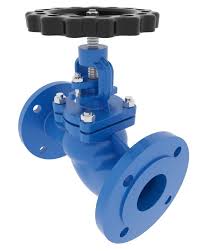
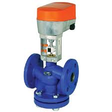
21/2″ Electric Globe Control Valves DN65
The Application of Electric Globe Control Valves
The application of Electric Globe Control Valves is vital for precise flow regulation in various industrial processes. Brands like Cameron offer advanced solutions including electric globe control valves and electric single seat type globe control valves, ensuring efficient operation and control. These valves incorporate electric actuators to automate flow adjustment, enhancing accuracy and reliability. Cameron’s technology ensures optimal performance, making them a preferred choice in industries such as oil and gas, chemical processing, and water treatment.
What Are The Types Of Electric Globe Control Valves ?
- Electric Single Seat Type Globe Control Valve:
- Features a single seat design for precise flow control in applications requiring high accuracy.
- Electric Double Seat Type Globe Control Valve:
- Utilizes a double seat design for applications requiring bidirectional flow control or higher flow rates.
- Electric Three-Way Globe Control Valve:
- Designed for diverting or mixing flow in systems where multiple process streams need to be controlled.
- Electric Angle Type Globe Control Valve:
- Features an angled body design for installations where space constraints or piping layout considerations are a concern.
What Is Electric Globe Control Valves ?
Electric Globe Control Valves are precision instruments used to regulate the flow of fluids in industrial systems. They employ electric actuators to adjust the position of the valve plug, allowing for accurate control of flow rate and pressure. These valves, including the electric single seat type globe control valve, ensure efficient and automated operation in applications where precise flow control is essential.
How to Select the Right Electric Globe Control Valves ?
To select the right Electric Globe Control Valves, consider factors like flow requirements, pressure ratings, and compatibility with the application. Ensure the valve type, such as the electric single seat type globe control valve, aligns with process specifications. Cameron offers a range of options known for reliability and precision, making them a trusted choice for various industrial applications.
Features of Electric Globe Control Valves
- Precision Control:
- Ensure accurate regulation of fluid flow, vital for maintaining process parameters within tight tolerances.
- Automation:
- Incorporate electric actuators for automated operation, reducing manual intervention and enhancing process efficiency.
- Versatility:
- Available in various configurations to suit different flow rates, pressure ranges, and fluid types, offering flexibility in application.
- Reliability:
- Provide dependable performance over extended periods, minimizing downtime and ensuring consistent operation.
- Ease of Integration:
- Designed for seamless integration with control systems and protocols, facilitating installation and setup.
- Safety:
- Equipped with safety features to prevent overpressure or leakage, enhancing operational safety and process integrity.
- Durability:
- Constructed from robust materials to withstand harsh operating conditions, ensuring long-term reliability and performance.
- Customization Options:
- Offer customization options such as valve size, material, and trim configurations to meet specific application requirements.
Advantages and Disadvantages of Electric Globe Control Valves
Advantages of Electric Globe Control Valves:
- Precision Control:
- Ensure accurate regulation of fluid flow, vital for maintaining process parameters within tight tolerances.
- Automation:
- Incorporate electric actuators for automated operation, reducing manual intervention and enhancing process efficiency.
- Versatility:
- Available in various configurations to suit different flow rates, pressure ranges, and fluid types, offering flexibility in application.
- Reliability:
- Provide dependable performance over extended periods, minimizing downtime and ensuring consistent operation.
Disadvantages of Electric Globe Control Valves:
- Initial Cost:
- The initial investment for electrically actuated valves can be higher compared to manually operated valves.
- Complexity:
- Require skilled personnel for installation, programming, and maintenance, adding to operational complexity.
- Power Dependency:
- Reliance on a continuous power supply for operation may pose a limitation in certain environments or during power outages.
- Potential Failure Points:
- Electrically actuated valves have more components and subsystems, increasing the potential for failure and requiring vigilant monitoring and maintenance.
The Specifications of Electric Globe Control Valves
| Specification | Details |
|---|---|
| Type | Electric Globe Control Valve |
| Ball Material | Stainless Steel (316) |
| Attachment Type | Flanged |
| Thread Standard | N/A |
| Thread Size | N/A |
| Body Material | Carbon Steel |
| Safe for Use With | Water, Oil, Gas |
| Handle Type | Electric Actuator |
| Handle Material | Stainless Steel |
| Maximum Working Pressure (psi) | 1500 psi |
| Maximum Working Pressure (bar) | 103.42 bar |
| Operating Pressure | 500 psi (34.47 bar) |
The Installation Steps for Electric Globe Control Valves
- Preparation:
- Gather all necessary components including the valve, electric actuator, mounting hardware, and tools.
- Ensure that the valve size, rating, and material are appropriate for the application.
- Mounting:
- Position the valve in the pipeline according to the piping layout and alignment requirements.
- Secure the valve to the pipeline using appropriate gaskets and bolts, ensuring proper alignment.
- Actuator Attachment:
- Attach the electric actuator to the valve bonnet or mounting bracket using the provided hardware.
- Align the actuator properly with the valve stem to ensure smooth operation.
- Electrical Connection:
- Connect the electrical wiring from the actuator to the power source or control system as per the manufacturer’s instructions.
- Ensure proper grounding and insulation to prevent electrical hazards.
- Calibration:
- Set the stroke and travel limits of the electric actuator according to the valve manufacturer’s specifications.
- Adjust the positioner settings for precise control and modulation of the valve.
- Testing:
- Conduct a functional test to verify proper operation of the valve and actuator.
- Ensure that the valve opens and closes smoothly in response to control signals.
- Sealing and Insulation:
- Apply sealant or gasket material as needed to prevent leaks at the flange connections.
- Insulate any exposed piping or components to protect against temperature fluctuations or external damage.
- Documentation:
- Record installation details including valve settings, wiring diagrams, and test results for future reference and maintenance.
The Operation Theory of Electric Globe Control Valves
- Valve Body: This is the main structure of the valve housing all the internal components. It typically consists of a globe-shaped chamber with inlet and outlet ports, as well as a movable disk or plug that controls the flow.
- Actuator: In electric globe control valves, the actuator is an electrical component responsible for moving the valve’s closure member (disk or plug) to adjust the flow rate. The actuator receives signals from a control system or operator and converts them into mechanical motion to open or close the valve.
- Closure Member: This is the part of the valve that regulates the flow by either obstructing or allowing passage through the valve body. In globe valves, the closure member is typically a disk or plug that moves perpendicular to the flow direction. By positioning the closure member, the flow rate can be controlled.
- Positioner (Optional): In some electric globe control valve setups, a positioner may be used to precisely control the position of the closure member based on feedback from sensors. The positioner ensures accurate positioning of the closure member according to the control signal received by the actuator.
- Control System: The control system provides the input signals to the actuator, which in turn adjusts the position of the closure member based on the desired flow rate or process conditions. The control system can be manual, pneumatic, or electronic, depending on the application requirements.
- Feedback Mechanism: In advanced systems, feedback mechanisms such as position sensors may be incorporated to provide real-time information about the position of the closure member. This feedback helps the control system to maintain precise control over the flow rate and respond to changes in process conditions.