
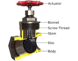
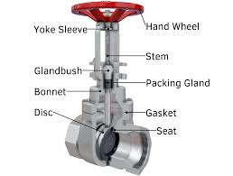
Gate Valve Components
The Application of Gate Valve
Gate valves, including knife gate valve components and API 6A gate valve components, play a vital role in fluid control systems. Cameron, a reputable brand, offers a range of gate valves designed for various applications. The components of gate valve typically include a body, bonnet, gate, stem, seat, and actuator. Knife gate valves feature a sharpened disc to cut through thick fluids and solids, making them ideal for slurry and wastewater applications. API 6A gate valves are robust and withstand high-pressure environments, commonly used in oil and gas drilling operations. With their sturdy construction and precise control, gate valves from Cameron ensure reliable performance in diverse industries.
What Are The Types Of Gate Valve?
- Rising Stem Gate Valve: In this type, the stem rises and lowers with the gate, providing a visual indication of the valve’s position.
- Non-Rising Stem Gate Valve: Unlike the rising stem valve, the stem of this type remains stationary while the gate moves up and down.
- Solid Wedge Gate Valve: Features a solid gate wedge design, suitable for handling clean fluids and preventing flow obstruction.
- Flexible Wedge Gate Valve: Incorporates a wedge with a slight flexibility, allowing it to compensate for any misalignment of the valve seats and body.
- Split Wedge Gate Valve: Utilizes a two-piece gate design that improves sealing performance and resistance to thermal expansion.
- Parallel Slide Gate Valve: The gate in this type of valve moves parallel to the flow direction, reducing wear and providing tight shutoff.
- Knife Gate Valve: Specifically designed for handling thick fluids and solids, featuring a sharp-edged gate to cut through debris and slurry.
- API 6A Gate Valve: Designed according to the American Petroleum Institute (API) standards for use in high-pressure and high-temperature environments, commonly found in oil and gas applications.
What Is Gate Valve?
Gate valves are essential components in fluid control systems, regulating flow by the vertical movement of a gate or wedge. This movement allows for complete shutoff or unrestricted flow. CV of a valve and calculating CV of control valve are vital in determining a gate valve’s capacity to control fluid flow rates under specific pressure conditions. Gate valves find extensive use in various industries due to their robust design, reliable performance, and ability to handle high-pressure applications with minimal pressure loss.
How Does Gate Valve?
Gate valves operate by raising or lowering a gate or wedge to control the flow of fluids. When the valve is open, the gate is lifted, allowing fluid to pass through freely. Conversely, when the valve is closed, the gate is lowered to obstruct the flow, providing a tight seal and preventing fluid passage. This simple yet effective mechanism allows gate valves to regulate flow rates and provide reliable shutoff in various industrial applications.
Features of Gate Valve
- Bidirectional Sealing: Gate valves provide bidirectional sealing, meaning they can effectively block flow in both directions, enhancing their versatility and suitability for various applications.
- Low Pressure Drop: Due to their streamlined flow path when fully open, gate valves typically exhibit low pressure drop, minimizing energy consumption and optimizing system efficiency.
- Robust Construction: Featuring sturdy materials such as stainless steel, cast iron, or brass, gate valves are built to withstand high pressures and temperatures, ensuring long-term reliability and durability.
- Full Port Design: With a full port design, gate valves offer unobstructed flow passage, allowing for maximum flow capacity and reducing the risk of flow restriction or turbulence.
- Precise Flow Control: By raising or lowering the gate, gate valves enable precise control over flow rates, allowing for gradual adjustments to meet specific process requirements.
- Quick Operation: Gate valves typically have relatively simple and quick operation, making them suitable for applications where rapid shutoff or opening is required.
- Various Types Available: There are several types of gate valves, including rising stem, non-rising stem, solid wedge, and flexible wedge, each offering unique features to suit different applications and operating conditions.
Advantages and Disadvantages of Gate Valve
Advantages:
- Excellent Sealing: Gate valves provide tight sealing when closed, minimizing leakage and ensuring reliable isolation of fluid flow.
- Low Pressure Drop: Due to their streamlined flow path, gate valves typically offer low pressure drop, optimizing system efficiency and reducing energy consumption.
- Suitable for High Pressure: Gate valves are well-suited for high-pressure applications, thanks to their robust construction and ability to withstand elevated pressures.
- Bi-Directional Flow: Gate valves can control flow in both directions, enhancing their versatility and applicability in various systems.
- Wide Range of Sizes: Gate valves are available in a wide range of sizes, from small to large diameters, making them suitable for diverse industrial applications.
Disadvantages:
- Slow Operation: Gate valves often have slower operation compared to other types of valves, especially in larger sizes, which may not be suitable for applications requiring rapid opening or closing.
- Risk of Jamming: In applications with high levels of sediment or debris, gate valves may be prone to jamming or fouling, affecting their performance and reliability.
- Not Suitable for Throttling: Gate valves are not ideal for throttling applications as they are designed for either fully open or fully closed positions, lacking precise flow control capabilities.
- Space Requirement: Gate valves typically require more space compared to other types of valves due to their design, which may limit their use in constrained installations.
The Specifications of Gate Valve
| Specification | Value |
|---|---|
| Type | Gate Valve |
| Body Material | Stainless Steel, Cast Iron, Brass, etc. |
| Attachment Type | Threaded, Flanged, Welded, etc. |
| Thread Standard | ANSI B1.20.1, BSPT, NPT, etc. |
| Thread Size | 1/2 inch, 3/4 inch, 1 inch, etc. |
| Ball Material | Not Applicable |
| Safe for Use With | Water, Oil, Gas, Steam, etc. |
| Handle Type | Handwheel, Gear Operated, etc. |
| Handle Material | Stainless Steel, Cast Iron, Plastic, etc. |
| Maximum Working Pressure (psi) | 150 psi, 300 psi, 600 psi, etc. |
| Maximum Working Pressure (bar) | 10.3 bar, 20.7 bar, 41.4 bar, etc. |
| Operating Pressure | 0-100 psi, 0-200 psi, 0-400 psi, etc. |
The Installation Steps for Gate Valve
- Preparation: Gather all necessary tools and equipment, including wrenches, pipe tape, and gaskets.
- Shut off System: Ensure the system where the valve will be installed is completely shut off and depressurized to prevent accidents.
- Positioning: Position the gate valve in the desired location within the pipeline, ensuring proper alignment with the flow direction indicated by the arrow on the valve body.
- Flange Alignment: Align the valve flanges with the corresponding flanges on the pipeline, ensuring proper alignment for a leak-free connection.
- Flange Connection: Secure the valve to the pipeline by tightening the flange bolts to the manufacturer’s specifications.
- Piping Connections: Connect the inlet and outlet piping to the valve using suitable fittings and pipe tape to ensure tight seals and prevent leaks.
- Stem Lubrication: Apply lubricant to the valve stem to ensure smooth operation and prevent seizing over time.
- Testing: Conduct a pressure test on the system to check for leaks and ensure proper valve operation before putting the system back into service.
- Final Checks: Verify that all connections are tight, and there are no visible signs of leaks or damage before returning the system to service.
The Operation Theory of Gate Valve
- Body: The main outer casing of the valve, which houses the internal components.
- Bonnet: Covers the top of the valve body and provides access to the internals.
- Gate or Wedge: The moving component that controls the flow by either blocking or allowing fluid passage.
- Stem: Connects the actuator (such as a handwheel or actuator) to the gate or wedge, allowing for manual or automated operation.
- Seat: The sealing surface against which the gate or wedge presses to form a tight seal when closed.
- Actuator: The mechanism used to operate the valve, such as a handwheel, gear operator, pneumatic actuator, or electric actuator.
The Parameters Chart of Gate Valve
| Parameter | Material Options |
|---|---|
| Body | Cast Iron, Ductile Iron, Carbon Steel, Stainless Steel, Brass, Bronze, PVC, etc. |
| Bonnet | Cast Iron, Ductile Iron, Carbon Steel, Stainless Steel, Brass, Bronze, PVC, etc. |
| Gate or Wedge | Stainless Steel, Brass, Bronze, Cast Iron, Ductile Iron, etc. |
| Stem | Stainless Steel, Carbon Steel, Brass, Bronze, Monel, etc. |
| Seat | Brass, Bronze, Stainless Steel, PTFE (Teflon), Rubber, EPDM, etc. |
| Actuator | Handwheel (Steel, Aluminum), Gear Operator (Steel, Aluminum), Electric Actuator (Aluminum, Stainless Steel), Pneumatic Actuator (Aluminum, Stainless Steel), etc. |