Differences Between a Regenerative Turbine Pump and a Centrifugal Pump
valve open or closed
What is a Regenerative Turbine Pump?
For Handling Liquid, regenerative turbine pumps fill a need between centrifugal and positive displacement designs. They combine high discharge pressure of displacement types with the flexible operation of centrifugals. They are a low-capacity high-head type used on heads up to 5400 ft (1645 m) and in capacities up to 150 gpm (34 m3/hr). Regenerative turbine pumps are known by several names, such as vortex, peripheral and regenerative. None of these give a true description of the pump, but regenerative turbine is the nearest. Several types of rotating pumps have been called “turbine”. Among them are the horizontal-shaft diffuser type and vertical-shaft deep-well centrifugal. The operation of the small pump with a big head, the regenerative turbine pump, is discussed here.
Regenerative Turbine Pump Design
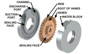
It show cross sections through a regenerative turbine pump. It shows the general construction to be quite like many small centrifugal designs. Its shaft, often made of stainless steel, is supported by two ball bearings. The impeller is overhung, a common construction for centrifugal pumps. The pump is generally supplied with a mechanical seal as standard. The chief difference between centrifugal and regenerative turbine pumps is in the impeller. In the regenerative turbine pump a double row of vanes is cut in the impeller’s rim. These vanes rotate in a channel, Liquid flows in at the suction and is picked up by the impeller’s vanes. After making nearly one revolution in the annular channel, the fluid has a high velocity that sends it out the discharge. Liquid entering a centrifugal pump’s impeller can pass between its vanes but once. It has energy added to it only while going from the impeller’s eye to its rim. In a regenerative turbine pump, liquid recirculates between the impeller’s vanes. Because of this action the fluid flows in a path like a screw thread (helical) as it is carried forward. Consequently, energy is added to the fluid in a regenerative motion by the impeller’s vanes as it travels from suction to discharge. This regenerative action has the same effect as multistaging in a centrifugal pump. In a multistage centrifugal, the fluid’s pressure is the result of energy added in the different stages. In the same way, in a regenerative turbine pump, pressure at its discharge is the result of energy added to the fluid by a number of impeller vanes.
How does a Regenerative Turbine pump work?
The primary difference between a centrifugal and a regenerative turbine pump is that fluid only travels through a centrifugal impeller once, while in a turbine, it takes many trips through the vanes. Referring to the cross-section diagram, the impeller vanes move within the flow-through area of the water channel passageway. Once the liquid enters the pump, it is directed into the vanes, which push the fluid forward and impart a centrifugal force outward to the impeller periphery. An orderly circulatory flow is therefore imposed by the impeller vane, which creates fluid velocity. Fluid velocity (or kinetic energy) is then available for conversion to flow and pressure depending on the external system’s flow resistance as diagrammed by a system curve.
It is useful to note at this point, that in order to prevent the internal loss of the pressure building capability of an MTH regenerative turbine, close internal clearances are required. In many cases, depending on the size of the pump, impeller to casing clearances may be as little as one-thousandth of an inch on each side. Therefore, these pumps are suitable for use only on applications with clean fluids and systems. In some cases, a suction strainer can be used successfully to protect the pump.
Next, as the circulatory flow is imposed on the fluid and it reaches the fluid channel periphery, it is then redirected by the specially shaped fluid channels, around the side of the impeller, and back into the I.D. of the turbine impeller vanes, where the process begins again. This cycle occurs many times as the fluid passes through the pump. Each trip through the vanes generates more fluid velocity, which can then be converted into more pressure. The multiple cycles through the turbine vanes are called regeneration, hence the name regenerative turbine. The overall result of this process is a pump with pressure building capability ten or more times that of a centrifugal pump with the same impeller diameter and speed.
In some competitive designs, you will find that only a single-sided impeller is used. That design suffers from a thrust load in the direction of the motor that must be carried by the motor bearings. MTH turbines use a two-sided floating impeller design that builds pressure equally on both sides. This has the advantage of allowing the pump pressure to hydraulically self-center the impeller in the close clearance impeller cavity, while not burdening the motor bearings with excessive thrust loads.
Regenerative Pump Construction
The pump has a vertical split case. By removing bolts B, cover C and liner L1 can be taken off to inspect or remove the impeller. To keep liquid flow small from high to low-pressure areas in the pump, the impeller has close clearance between liners L1 and L2.
Pressure on the Impeller
About one-half discharge pressure exists around the impeller’s hub, which is the pressure on the mechanical seal. Holes H through the impeller prevent unbalanced pressures on it and end thrust on the bearings. A small bypass flow also occurs across the sealing surfaces between the discharge and suction, Wear on these sealing surfaces increases the clearances and the bypass flow. The same thing happens at the sealing rings of centrifugal pumps. This wear reduces pump capacity greatly when operating at a high head. Most failures of regenerative turbine pumps are caused by this wear at the sealing surfaces. A study of the causes of wear belongs in a separate article where it can be discussed at length. However to prevent serious wear, don’t let the impeller touch liners L1 and L2 and be sure pumped liquid is free of abrasive material. Roth regenerative turbine pumps with patented self-centering impellers greatly reduce the wear problem.
REGENERATIVE PUMP DESIGN ADVANTAGES
- Develop higher pressures
- Can be run at lower motor speeds
- Eliminate cavitation
- Operate with lower NPSHr
- Deliver specified capacity with input pressure variations
- Meet performance with fewer stages
- Smaller size
What is a Centrifugal pump?
Centrifugal pumps are the most common type of pump used in industry, agriculture, municipal (water and wastewater plants), power generation plants, petroleum and many other industries. They are the primary pump type in the class of pumps called “kinetic” pumps and are distinctly different than “positive displacement” pumps.
How does a Centrifugal Pump Work?
Centrifugal pumps are hydraulically operated machines characterised by their ability to transmit energy to fluids (in particular to liquids) through the work of a field of centrifugal forces. Their main purpose is to transfer fluids through an increase in pressure. Centrifugal pumps can have different structures, but their operating principle and fluid dynamic characteristics are always the same. Schematically, centrifugal pumps are formed of an impeller that rotates inside the casing. The impeller comprises a series of blades, preferably of a radial design, which transmit kinetic energy to the fluid being pumped. The casing is equipped with suction and discharge nozzles for the fluid being pumped. The suction nozzle has an axis that corresponds with the impeller’s rotational axis, while the discharge nozzle has a normal axis to the impeller axis, but still lying on the plane passing through the axis itself.
Centrifugal Pumps Operating principle
The fluid being pumped enters continuously through the pump’s suction nozzle at the centre of the impeller. From here it is accelerated in a radial direction as far as the edge of the impeller, where it drains into the casing. The fluid current is accelerated by the push that the impeller blades, thanks to their curvature, transmit to the current itself. In this way the fluid acquires energy, mainly in the form of an increase in its average speed (kinetic energy). Inside the casing, the liquid is suitably slowed down thanks to the gradually growing section in the direction of motion.
Advantages of Centifrugal Pumps
- There are no drive seals, therefore the risk of leaks is completely eradicated. This means that hazardous liquids can be pumped without spillages. Eliminating the drive seals gets rid of leaks, friction loss, wear and noise and provides complete separation of fluid from the pump drive. This ensures that nearly 100% of the motor power is converted into pumping power.
- No heat transfer from the motor—the pump chamber is separated from the motor by an air gap; providing a thermal barrier.
- Complete separation from the process media means that liquid cannot seep into the motor from the pump.
- Reduced friction.
- Magnetic coupling can be broken if the load of the pump is too great. By the magnetic coupling ‘breaking’, it means the pump does not overload and get damaged.
Differences Between a Regenerative Turbine Pump and a Centrifugal Pump
Regenerative turbine pump have double row vanes cut in the rim. The impeller rotates within two liners into which annular channels have been milled. Liquid flows in at the suction and is picked up by the impeller vanes. In completing nearly one revolution in the annular channel, the fluid develops a high velocity and pressure increases dramatically before being sent out the discharge. The liquid re-circulates between the impeller vanes and the annular chamber. Because of this action, the fluid flows in a path like a helical spring laid into each of the annular grooves as the fluid is carried forward. Energy is added to the fluid by a number of vortex impulses in the impeller vanes, as it travels from suction to discharge.
These impulses have the same effect as multi- staging in a centrifugal pump. In a multistage centrifugal pump, the pressure is the result of energy added in each stage. In a turbine pump, pressure is added to the fluid stream by circulating many times through the vanes of a single impeller.
One of the most remarkable features of the regenerative turbine pump is its performance characteristics when pumping highly volatile liquids. The manner in which the turbine impeller imparts velocity/energy to the fluid, as described above, is quite different from conventional centrifugal or positive displacement designs. The continuous, progressive building of pressure in a regenerative turbine pump essentially eliminates the sudden collapse of bubbles that is destructive cavitation.
A turbine pump can develop about ten times the discharge pressure of a centrifugal type having equal impeller diameter and speed. Pressure increases nearly uniformly around the impeller rim. At the impeller hub, the pressure is about one half the discharge pressure. This lower pressure, plus suction pressure, is what is seen in the stuffing box. Holes through the impeller keep the impeller centered to reduce wear, prevent unbalanced pressures on the impeller and reduce end thrust on the bearings.