Three Ways Control Valves
The Application of Three Ways Control Valves
Cameron is a leading brand known for its innovative industrial solutions, including the versatile three-way control valve. Used in various applications, the pneumatic three-way control valve enables precise regulation of fluid flow in three directions. Its functionality is elucidated through a comprehensive three-way control valve diagram, aiding in understanding and maintenance. Cameron’s commitment to quality ensures efficient fluid control solutions for diverse industries.
What Are The Types Of Three Ways Control Valves?
Three-way control valves typically come in two main types: mixing valves and diverting valves.
- Mixing Valves: These valves blend two streams of fluid to create a desired mixture or temperature. They have three ports: one inlet and two outlets. By adjusting the valve position, the operator can control the proportions of each fluid in the mixture.
- Diverting Valves: These valves redirect the flow of fluid from one inlet to one of two possible outlets. They also feature three ports: one inlet and two outlets. The valve position determines which outlet the fluid flows to, allowing for flexible control over process flow direction.
Trim
Valve plug
Three-way, V-port with linear characteristics
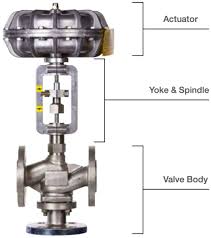
Actuator
Type
Single-acting diaphragm actuator, Spring type piston
actuator, Double acting piton actuator
Diaphragm material
Cloth embedded nylon and ethylene propylene rubber
Spring range
• 20 to 100 kPa(0.2 to 1.0 kgf/cm2)
• 40 to 200 kPa(0.4 to 2.0 kgf/cm2)
• 80 to 240 kPa(0.8 to 2.4 kgf/cm2)
Supply pressure
0.14, 0.25, 0.28, 0.4, 0.5 Mpa
Air connection
Rc1/4 or 1/4NPT internal thread
Ambient temperature
-30 to 70℃
Valve action
• FO: Air to close(Direct action actuator is combined.)
• FC: Air to open(Reverse action actuator is combined.)
Optional accessories
• P/P or I/P Positioner
• Air filter regulator
• Top-mounted or Side-mounted Handwheel
• Limit switch
• Solenoid valve
• Motion transmitter
• Booster relay
• Lock-up valve
• Airlock relay
• Others
Performance
Rated Kv value
Refer to table 1.
Flow characteristics (Refer to table 2)
• Linear
Leakage
• Metal Seat
According to IEC 60534-4:2006 Class IV, leakage less
than 0.01% of maximum valve capacity.
Inherent rangeability
• 30:1
Hysteresis error
• Without positioner: Within 3% F.S.
• With positioner: Within 1% F.S.
Linearity
Without positioner: Within ±5% F.S.
With positioner: Within ±1% F.S.
What Is Three Ways Control Valves?
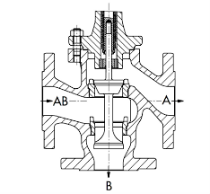
Three-way control valves are specialized components used in fluid control systems to manage the flow of fluids in three different directions. These valves typically have three ports: an inlet and two outlets. They are crucial for applications requiring diversion, mixing, or blending of fluids. By adjusting the valve position, operators can regulate the flow rates and directions of the fluids, ensuring precise control over the process.
How to Select the Right Three Ways Control Valves?
Selecting the right three-way control valve involves considering factors such as the application requirements, fluid properties, pressure and temperature conditions, and desired flow rates. Evaluate compatibility with existing systems, control mechanisms, and maintenance requirements. Consulting with experienced engineers or valve specialists can provide valuable insights for optimal selection.
Features of Three Ways Control Valves
- Versatility: Three-way control valves offer versatile fluid control capabilities, allowing for diversion, mixing, or blending of fluids to meet diverse process requirements.
- Precision: These valves provide precise control over flow rates and directions, ensuring optimal process performance and efficiency.
- Compact Design: Their compact design minimizes space requirements, making them suitable for installations where space is limited.
- Flexible Operation: With options for manual, pneumatic, or electric actuation, these valves offer flexibility in operation, catering to different automation needs.
- Durability: Constructed from high-quality materials, three-way control valves exhibit robustness and longevity, even in demanding industrial environments.
- Easy Maintenance: Their design facilitates easy access to internal components for maintenance and repair, minimizing downtime and operational disruptions.
- Customization: Manufacturers often offer options for customization to tailor the valve specifications to specific application requirements, enhancing performance and efficiency.
Advantages and Disadvantages of Three Ways Control Valves
Advantages:
- Versatility: Three-way control valves offer versatility in fluid control, enabling diversion, mixing, or blending of fluids in a single valve.
- Space Efficiency: They often have a compact design, minimizing space requirements in installations where space is limited.
- Precise Control: These valves provide precise control over flow rates and directions, ensuring optimal process performance and efficiency.
Disadvantages:
- Complexity: Their three-port design can introduce complexity to the system, requiring careful consideration during installation and operation.
- Higher Cost: Three-way control valves may be more expensive compared to simpler valve types due to their advanced functionality and features.
- Maintenance: Maintenance and repair of three-way control valves may be more challenging and time-consuming compared to simpler valve types, especially in systems with complex configurations.
The Specifications of Three Ways Control Valves
| Specification | Details |
|---|---|
| Type | Three-Way Control Valve |
| Ball Material | Stainless Steel, Brass, or PVC |
| Attachment Type | Threaded or Flanged |
| Thread Standard | NPT (National Pipe Thread) |
| Thread Size | 1/4″, 3/8″, 1/2″, or customized |
| Body Material | Brass, Stainless Steel, PVC, etc. |
| Safe for Use With | Water, Air, Oil, Chemicals, etc. |
| Handle Type | Lever, Knob, or Actuator |
| Handle Material | Plastic, Aluminum, Stainless Steel |
| Maximum Working Pressure psi | Up to 5000 psi (varies by model) |
| Maximum Working Pressure bar | Up to 345 bar (varies by model) |
| Operating Pressure | Dependent on system requirements |
The Installation Steps for Three Ways Control Valves
- Preparation:
- Gather all necessary tools and equipment, including wrenches, thread sealant, and pipe fittings.
- Ensure the work area is clean and free from debris.
- Valve Inspection:
- Examine the valve for any visible damage or defects.
- Verify that the valve specifications match the requirements of the system.
- Select Location:
- Choose an appropriate location for installing the valve, considering accessibility and operational requirements.
- Ensure sufficient space for maintenance and operation.
- Shut Off System:
- Shut off the flow of fluid to the system where the valve will be installed.
- Release any pressure in the system to prevent accidents during installation.
- Prepare Pipes:
- Clean the pipe ends thoroughly to remove any dirt or debris.
- Apply thread sealant or tape to the male threads of the pipes.
- Mount Valve:
- Position the valve in the desired orientation on the pipeline.
- Use appropriate fittings to secure the valve to the pipeline, ensuring a tight seal.
- Connect Pipes:
- Screw the pipe ends into the valve ports, ensuring proper alignment and tightening to prevent leaks.
- Use a wrench to tighten the connections securely, but avoid over-tightening.
- Test for Leaks:
- Once the valve is installed, pressurize the system and check for any leaks around the valve connections.
- If leaks are detected, tighten the connections further or apply additional sealant as needed.
- Final Checks:
- Confirm that the valve operates smoothly and functions correctly in diverting, mixing, or blending fluids.
- Label the valve for easy identification and maintenance in the future.
- System Activation:
- Restore the flow of fluid to the system and verify that the valve operates as expected under normal operating conditions.
The Operation Theory of Three Ways Control Valves
- Flow Diversion:
- In a three-way hydraulic control valve, fluid can be directed to one of two possible outlets while maintaining a single inlet.
- By adjusting the valve position, operators can control which outlet receives the fluid flow, effectively diverting it as needed.
- Flow Mixing:
- These valves facilitate the mixing of two streams of fluid from separate inlets into a single outlet.
- By regulating the valve position, operators can control the proportions of each fluid in the mixture, enabling precise blending as required by the process.
- Control Mechanism:
- The operation of three-way hydraulic control valves relies on a control mechanism, which can be manual, pneumatic, or electric.
- Manual control typically involves a lever or knob that adjusts the valve position manually.
- Pneumatic or electric control allows for automated adjustment of the valve position based on signals from sensors or control systems, enhancing precision and efficiency in fluid control.
- Application:
- Three-way hydraulic control valves find application in various hydraulic systems where diversion, mixing, or blending of fluids is necessary.
- Common applications include hydraulic circuits in industrial machinery, hydraulic power units, and hydraulic control systems in aerospace and automotive industries.
The Parameters Chart of Three Ways Control Valves
| Parameter | Description |
|---|---|
| Valve Type | Three-Way Control Valve |
| Body Material | Stainless Steel, Brass, PVC, etc. |
| Ball Material | Stainless Steel, Brass, PVC, etc. |
| Stem Material | Stainless Steel, Brass, etc. |
| Seat Material | PTFE, EPDM, Viton, etc. |
| Seal Material | Nitrile, Viton, EPDM, etc. |
| Actuator Type | Pneumatic, Electric, Manual |
| Actuator Material | Aluminum, Stainless Steel, Plastic, etc. |
| Connection Type | Threaded, Flanged, Welded, etc. |
| Thread Standard | NPT, BSP, BSPT, DIN, etc. |
| Pressure Rating | Up to XXX psi/bar (varies by model) |
| Temperature Rating | Up to XXX °C/°F (varies by model) |
| Size Range | 1/4″ to X” (varies by model) |
| Flow Capacity | Dependent on valve size and design |
| Leakage Class | ANSI Class IV, V, VI, etc. |